Remembering steps for a new project
- Define objective (e.g. send string to LCD, use it as a debugging device)
- Read sample projects
- Very high level circuit on paper
- List components (order if needed)
- Read datasheets of key components
- Software (C program, makefile etc.)
- Join components on Breadboard - working circuit (test individual components if new e.g LED test for new microcontroller)
- Final breadboard circuit (tested)
- Schematic (Kicad)
- Symbol/Footprint creation and mapping
- Layout
- Gerbers
- Order PCB
- Solder components on PCB
- Test PCB
This project has been done till breadboard testing so till step 8.
Objective
To learn interfacing with an LCD and make it available to be used as a debugger for future projects
Sample projects
New LCD procured. Already had ATMega328 (2 pc).
High level circuit on paper
 |
Understanding of new components
ATMega328
Quick comparison between atmega32 (previously used) and atmega328 (used in this project)
- Max clock: 16 MHz vs 20 MHz
- Interrupt and wake-up on pin change
- Minimum supply voltage: 2.7V vs 1.8V
- Atmega328 has extra fuse bit to state whether reset is used as normal reset or a GPIO pin
- Makefile is to be created keeping new fuse bits in mind
- Reset pullup resistor 30-85k v 30-60k in 328 (page 323)
- I/O pin pull up resistor 20-50k (same in both)
HD44780U datasheet - the main chip that interfaces between microcontroller and the display
- 8 data pins (D0-D7), can work with 4 (D4-D7, send upper 4 bits, then lower]
- 3 control pins (RS, RW, EN); 5 power supply related pins
- CGRAM (64 bytes), CGROM (1,240 bytes), DDRAM (80 bytes): all internal
- Main takeaway: LCD commands [pages 24 and 42]
- RS = 0 (command), 1 (data)
- RW = 0 (write), 1 (read) [can keep permanently 0 in this project]
- EN = make high (1) to send, wait for 100 uS, then make low (0)
- Put appropriate delay ms/us after each command
LCD commands (in sequence)
- Power supply [20 ms]
- Function set - set 8/4 bit, 1/2 line, 5*8/5*10 [37 us]
- Display on - cursor blink [37 us]
- Entry mode set - increment/decrement, shift left/right [37 us]
- Write data [41 us]
- Return home [1.52 ms]
- Set DDRAM address to move cursor to 2nd line [37 us]
- Clear display [10 ms]
- Cursor/display shift [37 us]
Soldering lcd pins

Not the best work. Did 3 times to reach a decent stage. First less solder, second more solder, third removed extra solder.
Test scenarios
Write to LCD
- One character (byte)
- One sentence with < 16 bytes
- One sentence with 16 bytes
- One word in 1st line & another word in 2nd line (move cursor manually). Both <=16 bytes.
- One sentence with >16 bytes & <= 32 bytes. Observe default behaviour. Does the 17th byte automatically goes to 2nd line? If not, code such that it wraps properly.
- One sentence with >32 bytes. Observe default behaviour. If needed, code such that display is intuitive
- Marquee (rolling/moving display)
- Clear display
- Blink cursor
- Shift/return home
- 4-bit transmission
How best to use as a debugging device:
Thought process
- Upto 32 bytes - simply use both lines
- 33-40 - use first line with rolling display
- >40 - no adequate setting found. Rolling both lines is not readable. If characters are shifted, you lose either the starting or the ending characters
After observing default behaviours and trying coding, decided to use the LCD in upto 32 bytes mode using both lines to the fullest.
No rolling display - adding rolling display for 8 bits did not seem worth as it also keeps the microcontroller busy.
Restrict message length to 32 bytes using the code.
Add default delay so each message stays for enough time to read. Add more delays with specific messages as needed.
V0 is grounded means maximum contrast. Tried potentiometer on V0 pin but it only dims the characters - not the backlight of LCD. As such the characters are not visible from a distance and from a number of angles so no requirement of dimming them.
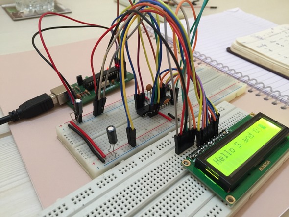
Breadboard
 |
| First look - priceless! |
The circuit worked but the LCD was displaying garbage characters on microcontroller reset (via the pushbutton). Problem of loose connection somewhere.
Re-did the circuit to avoid loose connections. Replaced jumper wires with solid ones, used two similar breadboards that 'click' into each other.
 |
| Old |
 |
| New |
Moved to binary (from hexadecimal). Made life much easier.
Golden rules of bitwise masking:
- Data remains as-is when ANDing with '1111'
- Data remains as-is when ORing with '0000'
The circuit worked whenever power was switched from off to on but the LCD displayed garbage characters on microcontroller reset (via pushbutton or make flash - without power reset).
Problem of garbage characters at reset
Tried the following without success:
- Extra 10uF capacitors at each power supply handshake between breadboards
- 0.1 uF capacitor between power supply and ground of LCD
- 1K resistor between enable pin and ground on LCD (this reduces the error to some extent i.e., LCD working fine on reset 2-5 times but not afterwards)
- Initialise before printing each time in code
- Extra delays (much more than what is prescribed in datasheet) at each command to LCD
Finally found the solution on this page. Appeared on 'page 2' of google search.
Basically at every reset, the LCD needs to revert to factory default (which is 8-bit, 1 line, 5*8 font). This means it needs to be addressed in this (8-bit) mode first and then be changed to 4-bit.
This was done by sending an extra 0x33 in command mode (0x30 also works as last two bits are don't care). 0x32 does not work.
Retained the 0.1uF cap and 1K resistor (# 2 and 3 above). Also, added an LED (red with 150 ohm resistor) on one of the free GPIO pins (PB0) to ensure the microcontroller is working fine even when the LCD shows garbage.
Wrapper function
This was easy - moved all functions to a header file which can be included in a .C file and functions (Initialise, writeToLCD) can be called via main.
Thought of adding delay as an argument while calling writeToLCD. However, custom delay did not work with standard _delay_ms functions. They expect constants (available at compile time) only and not variables (available at run time). Workaround: add default delay in 'writetoLCD' function + add additional delay in calling function if you want a particular error message to stay on for longer.
The LCD (both hardware and software) is now available to be used as a debugger.


Sending 'numbers' to LCD - The standard function snprintf can be used to convert string to number.
To make this project on a professional PCB, best to approach Lioncircuits. They even offer procurement of the components used in this project.
Link to previous project: Blinky
Link to next project: Happy Hour
No comments:
Post a Comment