Objective
Key components

Components functionality - initial understanding
- Mic [on + record]
- capture human audible frequencies (20 hz - 20 khz)
- specially 1-2 khz
- ADC [on + record]
- Mic output voltage convert to digital stream
- resolution
- sampling frquency
- MP3 Encoder [on + record]
- can be software or hardware
- digital output of ADC to .mp3
- Microcontroller
- [on + record]
- store mp3 in memory (circular buffer)
- [on + play / error] fetch mp3 from memory, supply to decoder
- [on + share]
- enter access point+server mode
- make audio recording (mp3) available on web page (with size and timestamp)
- [initiated on web page]
- update wifi settings/radio url in memory
- Perform OTA upgrade (enter station mode and connect to router, initiate https OTA API)
- [on + radio]
- enter station mode and connect to router
- get radio stream and buffer (as needed)
- play radio stream
- MP3 Decoder [on + play / error / radio]
- can be software / hardware
- decode mp3 to playable digital stream
- DAC [on + play / error / radio]
- convert decoder output (digital stream) to analog voltages
- resolution
- Amplifier [on + play / error / radio]
- DAC output amplification of voltage
- Speaker [on + play / error / radio]
- amplifier output to sound waves
- respond to volume control
- Memory
- store audio recording in loop
- store error(x).mp3
- store radio buffering (if required)
- store wifi credentials (microcontroller and external router)
- store webpage data (if required)
- store audio recording size and timestamp
- store radio URL
- store software version
- store any other metadata
- Power management
- battery rechargeable
- voltage regulation
- charging mechanism - microusb connector
- battery low / full indicator - RGB led
- User input
- [record button] audible sound
- [play button] full recording play via speaker
- [share button] connect and view web page
- [radio button] play radio via speaker
- volume control, on/off button (switch debouncer)
- Webpage [on share]
- show list of audio recordings with size and timestamp
- play audio recording
- download audio recording
- update wifi settings (microcontroller and external router)
- update radio url
- upgrade - software version as read-only display
- Router
- provide connection to
- internet - radio server [on + radio]
- https server running on computer [on upgrade]
- Mobile [on share]
- connect to esp wifi
- open esp ip webpage
Other audio recorder modules that could be explored in future:
- ISD1820: calcuttaelectronics, components101, amazon
- ISD1760: electronicscomp, datasheet
- ISD1806: amazon
Chosen VS1053 because the quality of documentation, support group and open-ness about internal workings, format used etc.
Mini projects
- Hello mic and speaker
- ESP8266: enter access point mode, server mode [on button press], show webpage with text 'hello world' via an IP address
- Save .txt in memory and display on webpage
- Save multiple files in memory and retrieve (hello file system)
- Capture user button press on web page and retrieve user submitted info
- Enter station mode and connect to internet router, get text from example.com
- OTA upgrade
- Digital audio play mic --> vs1053 board --> speaker (ESP in between)
- User input with ESP GPIOs with switch debouncer
- Digital audio: file encoding
- Internet radio: decoding and playing
- Battery indicator with LEDs
Introduction to esp8266
FreeRTOS notes - notes from official documents
ESP8266 examples - experience with the official examples (RTOS SDK)
Using nodemcu module which in turn has esp-12e module of esp8266.
Introduction to audio
- intro to sound formats
- mp3 and aac explained (digikey)
- audio file size calculator
- audio formats and file types
- vs1053 board - sparkfun link
- vs1053 LC technology board schematic

VS1053 notes from datasheet
- Suggested schematic vs actual, when design yours, understand purpose of each component & hence the chosen value
- GBUF usage, common voltage, to eliminate need of large isolation capacitors for earphones - not clear
- LINE IN and mic should not be connected at same time - how to disable one when other in use
- DREQ usage - start (or finish) next sci/sdi operation after checking the status of dreq - not clear why finish word is used
- SDI is for audio data
- byteRate? fast playback? playSpeed? absolute play position? positionMSec? mentioned in decode_time
- how much speed is increased by playspeed? how to calc if uC can send data for fast play (expected by vs)
- wram and wram_addr: X/Y memory, instruction word 32 bits
- Decode_time can be used to change bitrate
- do we need to fill AI_ADDRR with same info as WRAMADDR? application notes
- page 48 - what is the benefit of putting higher (24MHz) freq?
- Hw reset doubles as full power down vs low power mode (power vs time to get back)
- fast fwd and rewind without audio
- SPI speed should match the bitrate
- checking 2 word (32 bit) variables twice to ensure value of high bit has not changed (by the time you get to it after reading low byte) - not clear, pg 58
- extra parameters: latestjump not clear, jumppoints - exact implementation not clear
ESP8266 with VS1053
Sample projects
1. Sample project (Arduino code) to play mp3 (hardcoded) - baldram’s (most useful)
2. Link explaining a problem with vs1053 module board & provides fix (hardware as well as a software) - incorporated in baldram’s code
3. Arduino project to setup single radio station - based on baldram’s code
4. Project using esp32 freertos sdk api - based on baldram’s code, adds infrared etc. support
5. Code connecting nodemcu with vs1053 - clarity of spi pins on nodemcu
6. Understanding of SPI clock polarity and phase
About the first (baldram's) sample project
- Arduino spi.cpp - implementation of all important SPI functions
- Arduino esp8266_peri.h having mapping of Arduino and ESP8266 registers. Using this file along with spi_register.h (from RTOS SDK API), you can figure our ESP register names & their purpose (to some extent)
- This code plays a hardcoded mp3 but for learning (and to be able to same in RTOS), modified code to just read and write vs1053 registers
Arduino (modified) code flow - just read and write registers
- Serial.begin (115200)
- VS hard reset - using gpio
- SPI.begin
- HSPI pins setup (SCK, MOSI, MISO)
- setFrequency 1 MHz
- Register settings (SPI1C=0, SPI1U=MOSI|MISO|SSE, SPI1U1=MOSI|MISO, SPI1C1=0
- Player.begin
- set cs/dcs as o/p & 1, dreq as i/p; delay 100ms
- wait for dreq to be 1
- [called 3 times] [read_all_registers] —> loop on [read_register]
- control mode on
- SPI.beginTransaction: while (SPI1CMD & SPIBUSY) {} then apply settings (2 MHz, MSB 1st, SPI mode 0))
- cs=0, dcs=1
- SPI.write(3) - read instruction
- SPI.write(reg_address) // SPI1W0 (buffer register) = data
- SPI.transfer (0xFF<<8|0xFF) // SPI1W0 = data, ORing with FF is done to clear old values
- wait for dreq to be 1
- control mode off
- cs=1
- SPI.endTransaction // empty
- [called 1 time] write_register
- control mode on
- SPI.write(2)
- SPI.write(reg_address)
- SPI.write(value>>8) // SPI1W0 = data, calling ‘write’ instead of ‘transfer’
- SPI.write(value) // called 2 times to send 16 bits,
- wait for dreq to be 1
- control mode off
Key files referred in underlying esp rtos sdk api
- spi_struct.h: spi_dev_t structure represents all the esp registers
- spi.h: spi_config_t represents the interface
- spi_register.h: defines all low level bits within esp registers
- spi.c: creates object of spi_config_t —> spi_object_t that helps talk to the peripheral, once it has value, registers are filled using this object
Links on ESP SPI clock configuration registers
- Metalphreak’s explanation, implementation
- another implementation
- links to right arduino files
ESP SPI_CLOCK register
1 0000000000000 000011 000001 000011 (0x80003043) initial default = sysclk
0 0000000001001 100111 010011 100111 (0x2674e7) pre=9, clk_div = SPI_2MHz_DIV
0 0000000000000 100111 010011 100111 (0x274e7) pre=0, clk_div = SPI_2MHz_DIV
Reading right to left (lsb->msb): first 6 digits clkL, nxt 6 clkH, nxt 6 clkN, nxt 13 bits prescaler, last bit is 1 if = sysclk else 0
Clock = [ 80 / (clkN+1) ] / (prescaler+1)
SCI - serial command interface
Register read/write not working - observations & learnings
- esp spi_clock register understanding
- do not place printf/logd within ‘critical / high throughput sections’. In-fact be careful while putting anywhere in underlying API
- Keep upgrading to new sdk api (v3.3) & toolchain (v8.4.0), say once a month: espressif link. This solved one error (InStringFetchProhibited)
- If stuck in rtos sdk, try simple arduino code - to check your hardware connections etc.
- Bit-order: do not change this to 'MSB first' (let it be default 0 i.e., LSB first), just set byte-order to big-endian ('MSB first')
- When reading VS1053 registers, values are inconsistent at times, some garbage then ok, to mitigate, read twice and only conclude when two recently read values are same, added this check within read_register function, also used in write_register
- Bits handling: esp (RTOS API) expects 32 bit data structures within SPI but register addresses are 8 bits & register values are 16 bits; pay special attention to convert 32 bit data structures to 8/16 bits using bit-shift operators
- Error in underlying ESP RTOS SDK API, in spi.c, in spi_master_trans where it says ‘start transmission’, after ‘SPI[host]->cmd.usr = 1;’, there should be ‘while (SPI[host]->cmd.usr);’. This ensures the program waits till SPI transmission (MISO or MOSI) completes before proceeding further. In original file, this while statement is inside the next 'if statement' under ‘receive miso data’ (2 lines below); cut-paste is required. Whether it is miso/mosi, the code should wait for cmd.usr to become 0. This idea came from the Arduino code that was checking two registers 'while (SPI1CMD & SPIBUSY) {}' while writing. Issue has been raised with Espressif on Github.
- In Arduino code, SPI settings are applied (within SPI.beginTransaction) every time a read / write is called. In RTOS API, spi_init is done only once in the beginning (combining what is happening in SI.begin + SPI.beginTransaction). But that is fine. Arduino API caters to many uCs and peripherals so they may have reasons to implement it that way.
Final solution was a combination of upgrading the SDK API and toolchain, correcting the bit order & correcting the error in underlying SDK.
SDI - serial data interface
Data exchange not working - observations & learnings
VS can receive max 32 bytes of SDI data
ESP can send max 64 bytes
ESP SDI not working. Tried these things but did not work:
various ‘chunk sizes’ (8/16/32/64) while sending, various clock speeds, Arduino platform, different delays, different places for dreq wait etc.
Final solutions that worked (all 5 required)
- Patch (right after hard reset): set GPIO 0 & 1 to GND (problem with LC technology board): Link
- DCS pin not working on LC technology board: use ‘shared’ mode (setting at the beginning after hard reset): Link. Introduced separate functions control_mode_on/off, data_mode_on/off
- Updated write_register to remove check (read what was written) for WRAM register because it cannot be read back without changing the value of WRAMADDR - check introduced in separate function wram_read
- Updated read_register to remove check (read 20 times till 2 reads are equal) for WRAM register because it is too volatile (value changes unpredictably after first read)
- Updated write_register to remove check (read what was written) for SM_RESET bit in SCI_MODE register because it gets reset as soon as actual softreset happens
- Good frequency to test: Fs=6 (11,025 Hz), S (sine skip speed)=2 (overall hex value: C2); F=Fs*S/128 = 172 Hz
- Tested left & right channels with different frequencies, volume up and down
- SCI test did not work - but that is ok since SCI is tested otherwise via read/write registers

ADPCM recording & playing
- settings to start recording - straight from datasheet
- apply adpcm patch
- storing data
- sample buffer 1024*2 bytes, each block 256 bytes, header 60 bytes (lsb first)
- file size: sample rate 8KHz, bit depth 4 bits so ~32 kbps (32440 bits/s = 237.6 KB/min
- ~4 min recording in 1 MB (space available on esp inbuilt eeprom); 1 min = 1000 blocks, 15s = 250 blocks (start here)
- understand sample rate v audio length v storage space (record_time_size.ods)
ADPCM recording not working - observations & learnings
Links referred: Adafruit forum, Arduino forum, adafruit library
VS official patches: downloads & sample code (.c)
VSDSP official forum: vs1053 playback too fast, checklist of common ‘getting started’ problems
- function read_register_no_chk (no double checking of value) was returning 32 bits! we were reading last 16 that were always 0 (silly internal code mistake)
- The check "4th byte of each data block should be 0" (from datasheet) is getting lots of errors! tried clocks 2/4/5/8/16 with clockF 0x8800; settled on 10 MHz with x3.5+1 factor (default recommended in datasheet) as minimum errors but varies
- buffer overflow: esp is slower? played with clocks but no use: played with when to start reading (hdat1>256 & <896) - did not prevent overflow but returns minimum errors
> Above two points did not impact the final audio quality
- read only 256 bytes at a time or 512 bytes? no difference in quality, settled for 512 as more efficient to read more (50%) of the buffer in one go
- ‘puts’ does not work as it expects a string termination with 0x00 (or \0) - a normal occurrence in audio header/data
- ‘putc’ works, later replaced with ‘fwrite’ for efficiency
- ‘fread’ returns data in reverse byte order (due to little endian-ness of esp_ - need to flip each byte (link)
- code cleanup: hard_reset function also applies basic settings, separate header.h & c
- tried different sampling rates - observations (see 'record_time_size.ods' on github)
- this link has a # of solutions put in place by vlsi e.g. ready-made player from sd card, can look into this before implementing more features
- vs1053 board internal schematic link
- Finally what helped was: hard reset (+ patches) after recording and before playing. This is a must and led to successful playback

Ogg Vorbis
Chose Ogg Vorbis as VS1053 offers only this compression format for encoding. Discovered that mp3 encoding is quite a secret and not easy to replicate. Ogg Vorbis is open source and as good as (if not better) than mp3.
Intro videos from xiph.org, pdf from vlsi along with example code
Ogg Vorbis recording not working - observations & learnings
- problem 1: not playable file
- spi clk was at 2MHz, clockF at 4.5x, spi clk increased to 8 MHz for player
- problem 2: recording (& playing) but repeats, skipping, lot of noise & occasional repeats/skipping, crashes
- esp seems faster: fread replaced with fputc to slow down
- problem 3: recording but lot of noise & occasional repeats/skipping, crashes (unreliable)
- studied example code & incorporated encoder loop
- problem 4: recording fine but lot of noise
- replaced read/write with read/write_nochk (no double checking of value if read/written), added dreq after disabling interrupts & after loading plugin
- problem 5: recording fine (excellent once) but occasional noise and crashes
- added esp_logi (prints) after activating encoder (printing ctrl registers) & in loop (printing buffer status and 3 other variables)
- buffer size is <256 for ~100 times before it becomes ~2000, this repeats almost consistently till the number of blocks are read
- problem 6: recording decent but occasional noise and crashes, skipping with 16k profile
- powering off esp, vs & switching on (in that order) sometimes fixes the crash/noise problem
Things tried further on this profile
- fresh file with:simpler read/write registers
- checks for spi error
- buffer value = ffff error, ignore/re-read hdat1 if value>4095
- studied encoder plugin file in detail (in excel)
- plugin check (load full, read back full) - lots of errors, program restarts by watchdog
- plugin check (write 1 wram_section, read back and re-write whole section) - lots of errors, program restarts by watchdog
- plugin check (read each byte after write & re-write) - lots of errors, program restarts by watchdog
- dreq wait with delay and timeout (10/50 microseconds)
- removed decoder patch
- set DCS=1 right at the beginning & keep throughout
- write sdi_patch right at the beginning & keep throughout
- set SDI_SHARE right at the beginning & keep throughout
- delays at various places (within recording/playing loops)
Finally what worked seems to be a combination of using simpler read/write functions (without double checking), skipping garbage values in HDAT1, removing decoder patch, implementing proper dreq wait with delay & timeout, making key settings (DCS pin, SDI_patch, SDI_share) in the beginning.
Working fine with 8kq01/02/03. Reliable, no skipping/repeating, decent amplification (loud), not a lot of noise. Does not work fine on higher qualities.
SD card was not needed since 5 minutes of recording in ogg vorbis format is taking ~500 KB which can be stored on existing internal esp flash memory.

Loop recording
Links referred
- Useful link on vs-dsp forum
- xDCS=1
- Also has pcb tips:
- analog v digital GND planes/other differences
- separate linear regulators and corresponding caps for analog & digital
- Basic link on how ring buffer works in dashcam: record in small files, get rid of oldest to record more
- Another link on ring buffer in C on vs-dsp forum
- How to introduce delay in microseconds: esp32.com, tutorialspoint, geeksforgeeks
- Link on how to upload your own files from computer to esp8266 spiffs. This was explored so HTMLs can be created, pushed on esp32 internal memory so esp32 as an HTTP server could show it when requested by a client. Did not work as such. We ended up creating HTMLs within the code. Raw and tedius but allows you to insert dynamic data well
- How to create 2D array at run time - link from stackoverflow
- Add yield() or delay() inside your for or while loops that could take longer than, say 100ms. This is to give time to other tasks to run. Also to avoid reset due to watchdog timer. Github link. Also has ESP GPIO and other key information
Observations from looking at audio data in bytes (printed in hex)
- Ogg vorbis header size is 1368 bytes (consistently. no matter what the quality or duration of recording is)
- It has 3 occurrences of ‘Oggs’ followed by 'vorbis' with some bytes in between
- 4th ‘Oggs’ means beginning of audio data. This is then NOT followed by ‘vorbis’
- Each ‘Oggs’ occurrence means beginning of a new section (can call it a 'page')
Approach for ring buffer implementation
- Store header in a separate file
- Then store 7 ogg sections/pages (~100 blocks/15 s) in a file. Cut at 8th ‘Oggs’.
- While recording, maintain ogg_count going into a particular file, switch file after 8th ‘Oggs’
- Encoder is reading 2 blocks (512 bytes) at a time. Technically, ‘Oggs’ can appear at 2-block boundary - one should check partial occurrence at the end of one set of 2 blocks & then see if the pattern completes at the start of next set of 2 blocks. We put & then removed this check since it was too much code for a less probable scenario. At worst, a file will have 1 more ‘page’ & will be slightly bigger - not a problem.
- test with file ~100 blocks i.e., ~15 sec each
- fixed filenames (eg. 01.ogg)
- ring buffer is array of strings (filenames)
- oldest pointer - index of ‘next file to record to’ / ‘oldest file to play’
- Metadata about ring in spiffs file: oldest pointer, # of files, file names
- Final: Ring of 20 files, each having max 7 ogg sections i.e., ~15 s recording, size ~30k, so total ring size ~600k. Final quality: 8kq02
- Crash occurs if we try to increase ring size although SPIFFS partition available size is ~1300k.
Learnings while implementing above approach on ring buffer
- if you read filesize (using stat function) before closing the file, it won’t be accurate
- fclose() does not set the file pointer to null
- Laptop charging causes electrical interference leading to vs1053 failures (dreq timeout, nothing works)
- Nearby light switch on/off also leads vs1053 to fail while recording / playing
- fread/fwrite return # of bytes written / read. Always put error handling using that
- copy header in each file while recording - output quality bad (noise and skipping)
- copy header offline (after encoder is done) using fread - error
- copy header offline using fputc - extremely slow / hangs, sometimes runs fine after erase_flash
- while changing # of files in ring buffer, if you move from larger (say 30) # to smaller (say 25), extra files (26-29) will have to be deleted manually (individually or erase_flash)
- Player can play with one header & then all files one by one & then finally send endfillbytes only once! This is the single biggest learning that eliminates the need to copy the header altogether!
- Recording quality also improved with this change: ~0 skips, no error even without erase_flash, good quality (less noise) - code v18
- v19 - introduced separate play_file function: ‘almost’ same quality

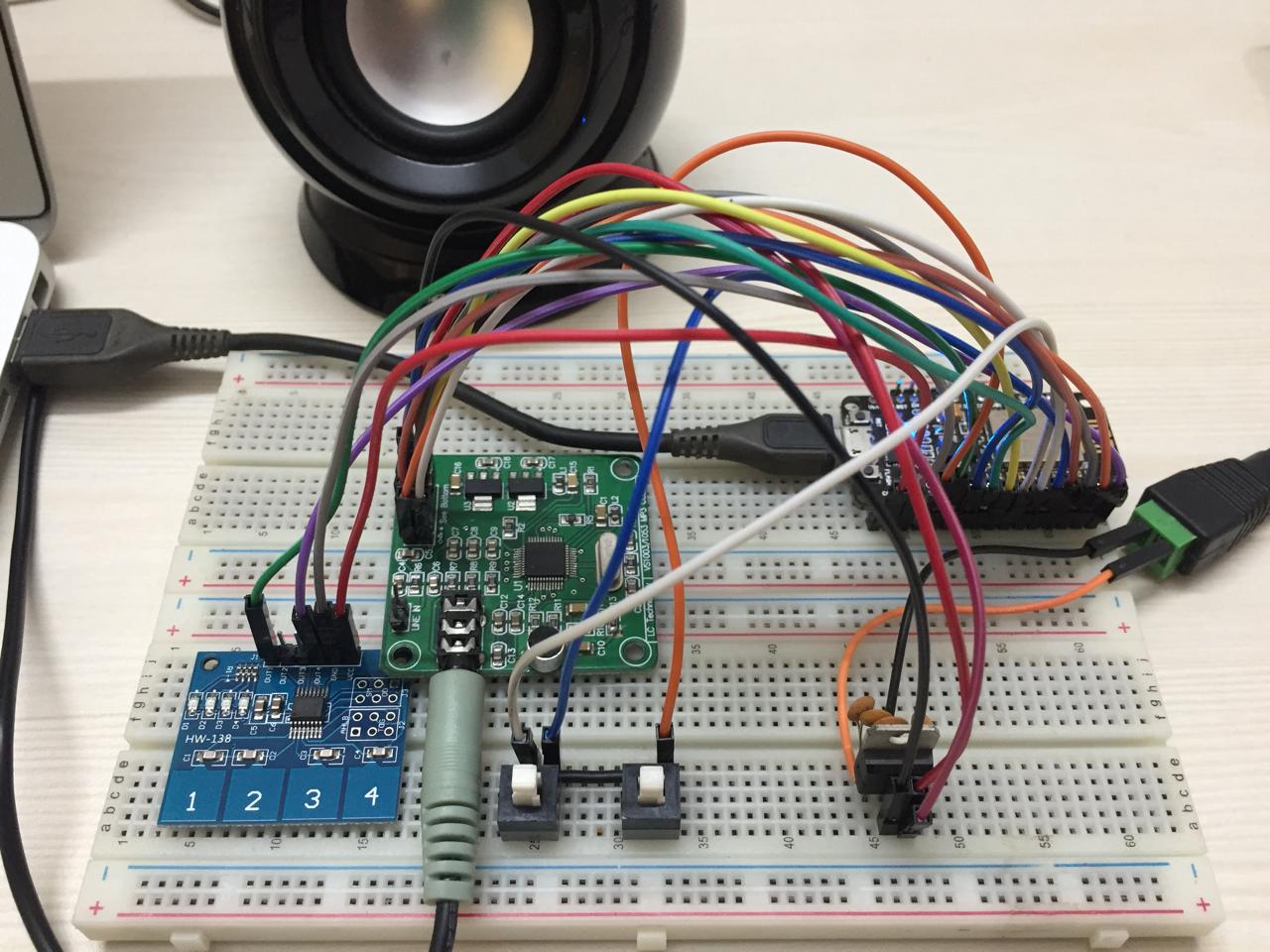
Introducing buttons
To start/stop recording, playing. Also to do next file/previous file.
Links on esp8266 gpio pins: esp8266 official forum, rabbithole, github, randomnerdtutorials, instructables, randomnerdtutorials2, techtutorialsx, electronicwings
Only 4 GPIOs left available to use. Used GPIO 2, 3, 15 and 16.
Links on capacitive touch sensor buttons: electroncomponents, electronicscomp, instructables, Julian Lett’s review of the TP224 based 4-touch button module, Great Scott’s how to make your own capacitive touch button
Other links: Mini push button, assorted kit with some caps, self-lock with cap, smd push button, Black Push Button Cap, Black push button switch
Tried three types of buttons: membrane buttons (pair of 4), touch buttons (pair of 4), DPDT self-locking switch (like the ones used in previous projects). Experience:
- Problems in booting when membrane/touch buttons were attached
- the membrane and touch buttons try to pull gpio pin low if Vref=GND (or high if Vref=Vcc)
- this problem does not exist with DPDT self-locking switch type buttons
- esp has rules about gpio pins i.e., they should be high / low during booting
- Not all gpio has ISR e.g. GPIO 16. solution: continuous polling using while (1)
- depending on the states of button (initial & when button pressed), negative / positive edge triggered interrupt type is used
- can’t write big code in ISR - just xSendQueue (or a little bit more)
- can’t use printf in ISR, have to use queues
- to avoid task watchdog crash, put delay in while (1) in main so the task gives space to other tasks / task scheduler. taskYield() does not prevent task watchdog
Finalised 2 DPDT self locking switches for recorder and player & 2 touch buttons to jump to next/previous file while playing.
Switch debouncing (using software): global variables updated in ISRs, referred (& also updated) in tasks
Four states for recording
- ISR (when button pressed down): recorder_off (0) —> start_recording (1)
- Recorder: start_recording(1) —> started_recording(2) {after setup which also introduces sufficient delay to avoid debounce}
- ISR(when button pressed up): started_recording(2) —> stop_recording(3)
- Recorder: stop_recording(3)—>recorder_off(0) {after soft stop & cleanup which also introduces sufficient delay to avoid debounce}
Similar states for playing.
- No need to stop player automatically after ‘last’ file. Play continuously until stop button is pressed manually.
- Inter button ISR handling: Entertain ‘start_recording’ only when player is off. Similarly entertain ‘start_playing’ only when recorder is off.
Creating separate vs1053.h
Linker errors: studied usage of ‘static’ and ‘extern’
- problem: if in vs.h & no ‘static’, linker error; if static in vs.h, ISR in main can’t change value of global variable!
- solution: declaring with extern in vs.h, defining in main, vs.c can then use it without declaring / defining
Webserver (sharing, AP mode)
- Reviewed esp_http_server
- webpage: display list of files with play & download links, oldest on top, download all link
- creating html as a string in code
- handler receives filename as param, opens file, reads bytes and send via http_send_chunk
- sending uri using request query param so 1 uri handler can be used for all files
- Not using a button to start/stop sharing since gpio 16 does not have ISR, so sharing remains always ON, continuous polling will keep main alive. Can keep WIFI AP mode continuously ON instead. Esp seems to have no problem in that. No other gpio available.
- when internet radio (i.e., STN mode) is switched on (manually), switch off AP mode (automatically), play radio, when radio is switched off (manually), switch AP mode back on (automatically)
Internet radio (STN mode)
Example project: Ka-Radio
Multiple radio stations along with details (format etc.)
Learnings while implementing
- while receiving from socket, we specify length, it will return <= len bytes (but when error it can return ffff also! handle that error in code e.g. skip and continue)
- header separated (based on search \r\n\r\n), length varies from ~300 to >1500, put max_header_len = 2048, within function, buffer is of 256 (>=512 gives crash - most probably memory related)
- multiple ISR handlers on same gpio are not allowed, last one over-rides
- Including port in radio stations: getting rid of ‘hints’ data structure & straightaway getting ip from name using dns server
- check from vs data sheet: bit rates across formats that are supported
- for AAC, decoder needs higher clock 4.5 at least, we are using this as default (instead of normal recommended 3.5+1)
Testing of various radio stations (radio browser)
- 0xffff in the beginning of many stations specially the ones in aac format
- ignoring it doesn’t help except in case of bbc radio
- header max size increased to 2048
- bbc working ok for 20-30 mins then silence - no error/crash
- ogg 128 works for 5-7 mins, then crashes
- task watchdog within micros function within us_delay within dreq_wait, solution: used taskyield instead of delay_us
- vs decoder patch does not help
Questions
- Why bbc stops after X mins?
- Why so many stations not working (ffff / bad response)
- What is ICY protocol?
- What is diff. b/w http 1.0/1.1? Link
- What is chunked encoding?
- MP3 sends some metadata after every X bytes, do we handle that?
- Shall we handle full variety of ratio stations with different URL, port, bitrate, playlist, autoplay, header, title, format?
- Edzelf code
Points from reading vs dsp forums
- The main problem-to-solve is buffering, flow control, out-of-phase packet assembly and error recovery
- link with buffer size suggestion / TCP receive window
- Find "ICY-Metaint" equals something in the headers. You need to strip away the ICY metadata packet at those byte intervals.
- clock speed hint: for aac only it seems
- May avoid initial burst of data (~50kb)?. Will this solve the ffff problem in many radio stations?
- Time when dreq goes up & time when we send data, should be analysed with a logic analyzer (later)
- Information on vs1053 pcb layout (later). VS as a chip has more pins than the LC board exposes. Think what all you can use in PCB eg. UART pins (RX/TX) to have debug info
- Information on sd card to vs1053 fast transfer on same SPI (later)
- events priority
Main takeaways / to-try
- recv_buf size should be large enough to store ~5s of audio data. 128kbps=16kB/s, 5s=80kB. ESP8266 ram is ~45kB so bitrate should be <=72kbps
- tcp socket buffer / tcp receive window (indication to sender how much data you can handle), RAM buffer. How to allocate 45 KB of RAM to tcp socket buffer?
- buffer underflow due to slow internet connection, may be clock can be increased further i.e., 5+0 (but this is mostly applicable to AAC only)
- icy-metaint=1 tells after how many bytes mp3 stream sends metadata. Not sure if this is needed since not much impact on playing even if we don’t handle that recurring metadata
- avoid initial burst of data (~50kb)?. Will this solve the ffff problem in many stations?
Decisions
- Limited bit rate (may be <72kbps)
- no playlist
- format mp3 only
- AP or STN mode at a time (not together)
- http 1.0 (no chunked encoding needed)
I/O/Task buffers & synch
- checking heapsize at various places. understanding individual tasks memory (heap/stack size etc.)
- need queue (FIFO) size as much as esp permits without crashing - 16k
- parallel tasks to load and unload audio data - same speed or which one higher? load as much as you receive, unload 32 bytes at a time
- initial load more - how much? 90% of queue, radio_task creates load, then waits till queue is 90% full, then creates unload
- understanding xTicksToWait:
- if this is infinite, task does not come out/do anything else. Remains in blocked state
- for recorder, if queue full, display error, and do what? discard bytes in hand, check radio state & fetch new
- for player, if queue empty, wait for how long? and then do what? 5s, check state: if still STARTED_RADIO, keep waiting, break otherwise
- Tests with various sizes of buffer/tcp/task, final settings:
- tcp task stack size: 2560->3840 (x1.5)
- main audio data buffer size: 512 —>16k
- radio task size: 2048 —> basic (without a big variable i.e., 1536)+queue size
- handling of internet connection not available at start / in the middle of radio
- use of wifi_stn_event_handler to change state & xQueueSend for radio_task (like ISR): default priority of an event handler is 10 (link). keep load/unload tasks priority < 10
- both load & unload tasks will detect the change in state, will do cleanups and delete themselves
- radio task will detect it’s queue (button press) and change state to OFF along with cleanups - should happen after load/unload delete themselves (introduce enough delays to ensure this or priority of radio_task could be set low)
- deleting load/unload tasks from radio_task often led to crash - this is because socket/queue gets deleted first! Options considered: suspend tasks instead of delete? don’t delete queue, just clear it up? not preferred due to their memory usage. Finally, using priorities and introducing enough delays helped.
Networks handling
- main does basic initializations like nvs, tcp, event loop, wifi_init with default config
- individual STN and AP start/stop functions do remaining settings: register events, set mode/id/pwd, start, connect
- softAP mode is ON default by main
- when radio_task starts radio, it first switches OFF AP & switches ON STN
- while stopping radio, it does the reverse
- No network reconnect attempt will be made from radio/load task. If connection is lost user needs to press radio button again when connection is restored OR restart the device
Possible future improvements in user interface
- LEDs with each major functionality e.g. radio on/radio off
- audio error messages: e.g. internet connection lost
- LOG file (available in AP mode via html - offline/live)
OTA
Key steps
- upgrade application in OTA_0
- Main application - good listener - in OTA_1
- when triggered, main app will change ota_data to OTA_0 and reset esp.
- Upgrade app will get latest app from driveopedia (http server) and ota_write to OTA_1. It will update ota_data to OTA_1 and reset esp
- custom partition table - taking care of offsets & sizes (final)
- make flash hello_ota into ota_0 - needs to be at least 500K
- .bin is enough .ota.bin not needed
- Noted header of a bin file
- API esp_ota_ops.h: ota.begin, ota.write, ota.end, ota.set_boot_partition, esp.restart
- About fatal errors
- put checks if running partition is ota_0 & update partition is ota_1 for sure
- the two ota partitions (ota_0 & ota_1) should be in continuous 1M partition each. Also, difference between offset of one & another must be 1M
- Explicitly ensure that the start of next ota partition is after 1024*1024 bytes. Put explicit offset (not mandatory in paritition.csv) otherwise system will fill it up wrongly.
- If you update partition.csv, do go to menuconfig & save so the system considers the updated csv. Also, do make erase_flash
- two separate spiffs partitions - one for ring, other for all other metadata including headerfile
- separate partition table for standalone application (to make flash)
- Ring with 20 spiffs files ~400K in a 440K partition leads to stack related error. Reduced to 10 files for the time being.
- currently: both ota - 600K, spiffs 430K, working fine but quality of recording seems to have deteriorated
- https://www.esp8266.com/viewtopic.php?p=80475
- Need esp8266 with 4M flash. SD card otherwise
Observations from testing
- Actually, our esp8266 based esp12E (part of nodemcu v1.0) has 4MB flash!! Can update in menuconfig-->serial flasher config
- partition tables adjusted for 4MB
- 20->40 files: worked fine
- 40->60 files: crash after 49 (stack overflow)
- recorder task stack size increased from 2048->5120, files 60->90: crash after 75 (fputc / spiffs error), some files took long to record (that’s where the problem is)
- fputc/spiffs error after #75 even if stack size is 8192: SPIFFS: failed to update mtime, error re-appears if you restart recorder (using button): To check
- in the mean time, limit files to 60, task stack size 8192
- radio did not work! no error/warning: noted from printfs that unload task could not get created, reduced recorder task stack size from 8192->4096, working fine
- webpage not working on iphone (may be just the play control). To check
At this point, most of the initial milestones/mini projects (except power management) are done. Next step is creating a product on PCB.
However, would like to create something useful, not just a replication of work done on breadboard so far.
Product idea based on audio reminders - product description
This required more breadboarding for new components like AVR, temperature sensor, RTC, 7-segment display, various buttons and LEDs.

Idea was to run all non-audio peripherals like temperature sensor and 7-segment display via AVR since ESP8266 is short on GPIOs.
AVR with temperature sensor - experience connecting LM335 with ATMega16
AVR with 7-segment display - experience connecting two 7-segment displays
Date-time capture in ESP8266 - no internal RTC, date-time keeping using software
Connecting ESP and AVR - experience with SPI, custom protocol, one button sending signals to two microcontrollers, capacitive touch buttons
The project was not continued all the way to PCB due to not enough GPIOs in esp8266, no easy connection between ATMega16 and ESP8266 & that we could not wait to move to our next project that involves video!
No comments:
Post a Comment